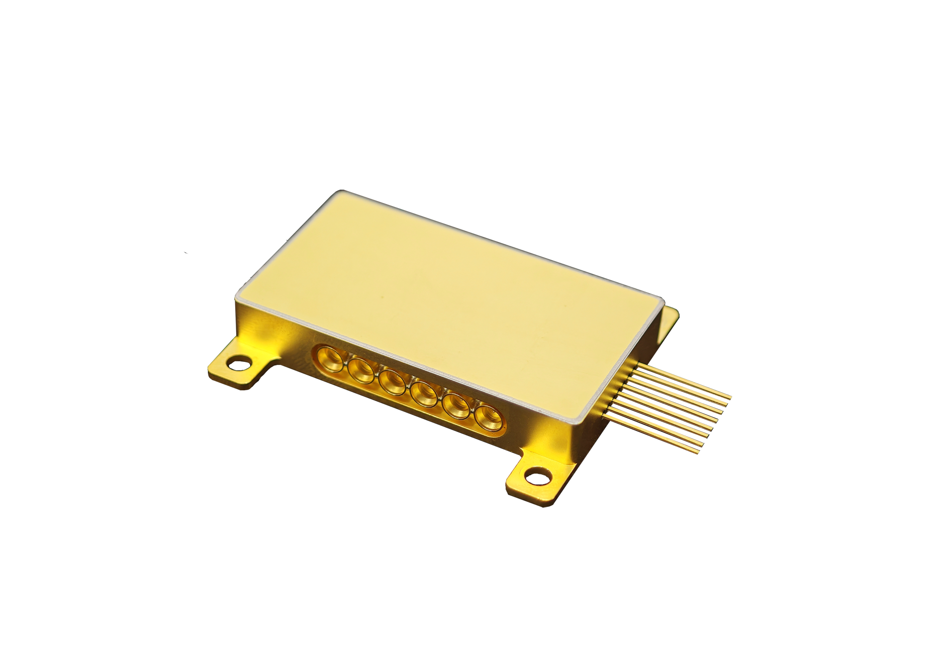
Bandwidth growth changes more than the headline rate of an optical link. As they add faster lanes and denser traffic, timing margin narrows, driver demands rise, and every decibel in the optical path becomes more useful. The modulator therefore sits at a sensitive boundary where electrical performance must be converted into a clean optical waveform.
Their evaluation cannot stop at a nominal gigahertz figure. Modulation format, symbol rate, packaging, connector transitions, laser quality, receiver tolerance, and digital signal processing all influence the data rate that a system can sustain.
A fast device with poor loss or unstable bias may create less usable capacity than a balanced component with controlled interfaces. Capacity models should include coding overhead, traffic burst behavior, and aging reserve, because nominal line rate does not equal sustained customer throughput.
Available TFLN Devices cover intensity, phase, IQ, and comb functions, with packaged bandwidth choices extending to 110 GHz. Those data serve as their engineering starting point. They then examine how voltage, insertion loss, linearity, thermal behavior, and assembly choices affect the network product that will be manufactured and supported.
Capacity Planning Begins at the Electrical-to-Optical Boundary
A high speed optical modulator matters because it must follow rapid voltage changes without rounding edges, compressing amplitude levels, or adding pattern-dependent distortion.
They translate the planned modulation format into an electrical spectrum and establish the response needed both at the delivered connector and at an internal chip reference plane that the board cannot access. TFLN devices become relevant when their electro-optic efficiency helps preserve both signal speed and power budget.
Lower half-wave voltage can reduce driver swing, while controlled insertion loss leaves more optical power for fiber, connectors, and receiver sensitivity. Neither benefit stands alone, so their architecture review combines electrical energy, optical margin, and error performance. Increasing lane rate also changes the tolerance for skew, reflection, and impedance discontinuity.
They model the package, cable, board launch, and driver as one channel, then compare simulation with measured S-parameters. This approach shows whether a bandwidth limitation belongs to the modulator itself or to the surrounding electrical path that can still be redesigned.
Published Bandwidth Has to Survive the Complete Assembly
For the highest-bandwidth listed intensity-modulator option, the 67/110 GHz product is specified with insertion loss below 4.5 dB and half-wave voltage below 3 V. This high-speed optical modulator offers a useful combination for demanding waveforms, but they still request response plots, reference-plane definitions, temperature data, and sample variation before assigning it to a specific transmitter design.
Within the broader TFLN device family, 40 GHz intensity, phase, and IQ options address different signal functions. A phase unit below 3.5 dB loss and 3.5 V half-wave voltage cannot be compared directly with an IQ circuit below 6.5 dB, because the latter integrates more optical paths and supports complex coherent formats.
Function must normalize the comparison. Optical-frequency-comb generation follows another trade-off. The listed 25 GHz RF bandwidth, voltage below 2.5 V, and loss below 9 dB support multi-line generation, yet line flatness, power per tone, phase noise, and long-term drift determine application value.
They therefore avoid treating a single bandwidth number as a universal indicator of system capability. They also compare equalizer complexity and driver headroom, since excessive electronic compensation can erase the power advantage expected from a faster optical component.
Commercial Readiness Depends on Repeatable Operating Margin
Qualification begins by operating a high-speed optical modulator with the intended driver, source, fibers, connectors, and receiver. They measure frequency response, eye quality, extinction, bias demand, optical loss, and error margin across voltage and temperature.
Repeating the procedure on several units reveals the distribution their production limits and controls must accommodate. At roadmap level, when TFLN devices enter a bandwidth plan, packaging consistency is as important as the selected prototype result. They compare lots, inspect coupling and RF transitions, and correlate wafer-level records with packaged performance.
Process-change notification, traceable assembly materials, and agreed acceptance data reduce the chance that a later build behaves differently from the qualification set. Operations teams also need practical diagnostics.
Bias telemetry, optical-power monitoring, alarm thresholds, and restart behavior help distinguish component drift from connector contamination or driver faults. They include these service requirements before design freeze, because a network product that cannot be diagnosed efficiently may consume more lifecycle cost than its initial performance advantage justifies.
Before committing a platform, finance and operations teams review qualification cost, spare policy, and expected service life alongside the engineering performance case. In practice, bandwidth growth is a system problem rather than a contest for the headline isolated specification.
They gain capacity when the modulator preserves the intended waveform with acceptable voltage, loss, thermal load, and manufacturing variation. Those conditions must remain true after the device is packaged, mounted, cabled, and operated under representative environmental limits.
Their decision process therefore connects traffic forecasts to modulation format, electrical channel design, optical budget, control strategy, qualification evidence, and supply continuity. This sequence prevents them from selecting a component that looks fast in a laboratory but leaves insufficient margin in the product architecture or creates an impractical production and support burden.
Bandwidth growth ultimately depends on usable electrical-to-optical margin, including the driver, package, receiver, and test method. Evaluating Liobate within that full budget shows whether the planned rate remains stable across manufacturing variation and temperature.
