Unexpected changes in weld quality can disrupt production long before a fault becomes obvious on the finished component. Fluctuating current readings, inconsistent waveforms, and unexplained alarms may point to electrical issues, worn electrodes, or incorrect measurement settings.
Investigating these symptoms becomes more straightforward when manufacturing teams work with a resistance welding monitor supplier that can clarify equipment behavior, check system compatibility, and offer practical guidance on data interpretation. Effective troubleshooting depends not only on identifying the faulty component but also on understanding how the monitoring system interacts with the wider welding process.
Diagnosing Measurement and Waveform Problems
Unusual waveform patterns often provide the first clue when welding performance changes. Sudden peaks, irregular current curves, or differences between consecutive cycles may reflect unstable contact conditions, changes in electrode pressure, or variations in the power supply. Engineers should compare abnormal records with waveforms collected during verified production conditions before adjusting machine settings.
Measurement accuracy also depends on sensor installation and configuration. Incorrect sensor positioning, loose connections, electrical interference, or unsuitable measurement ranges can distort the recorded signal. Checking these factors systematically helps technicians distinguish between an actual welding problem and an error introduced by the monitoring arrangement.
A qualified resistance welding monitor supplier should be able to explain how the equipment captures and processes electrical signals. Support may include reviewing waveform records, confirming measurement settings, and identifying possible causes of inconsistent readings. Such guidance allows maintenance teams to investigate problems methodically rather than replacing components based on assumptions.
Investigating Electrical Compatibility and Welding Conditions
The electrical configuration of a welding machine has a direct effect on the signals available for monitoring. Differences in current levels, waveform characteristics, and control methods can influence measurement results. Before diagnosing a fault, engineers should confirm that the selected sensors and input settings suit the equipment’s actual operating conditions.
The resistance welding transformer deserves particular attention during electrical troubleshooting. Its output characteristics, together with the secondary circuit and electrode connections, influence the current delivered to the workpiece. Loose connections, deteriorated conductors, or changes in circuit resistance may contribute to abnormal readings. Comparing primary and secondary circuit conditions, where suitable measurement methods are available, can help narrow the investigation.
AC and DC welding also require different considerations during signal analysis. AC waveforms vary periodically, while DC applications may show different current profiles and transient behavior. Multi-pulse welding introduces another layer of complexity because each pulse can serve a different function within the welding cycle. Technicians should confirm that the monitoring equipment’s analysis mode matches the process under investigation.
Using Data Analysis to Identify Recurring Faults
A single abnormal reading may result from a temporary disturbance, but repeated deviations can reveal a developing process problem. Reviewing historical records helps engineers identify whether irregularities occur at particular stations, after electrode changes, or during specific production runs. This comparison is especially useful in high-volume automotive, battery, and electronics manufacturing, where small variations can affect many components.
Understanding how resistance welding monitoring helps reduce weld defects can also help troubleshooting teams interpret abnormal signals and distinguish possible process variations from equipment-related problems.
Waveform displays and calculated values offer different perspectives on the same welding cycle. Peak values reveal the highest recorded levels, while root mean square (RMS) values describe the effective magnitude of an alternating signal over a defined interval. Neither value explains every possible defect, so engineers should interpret these measurements alongside cycle duration, process settings, and inspection results.
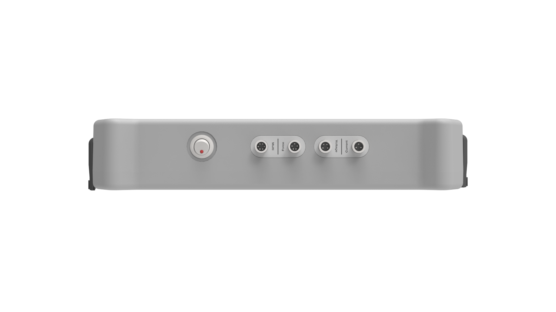
Communication features can also affect troubleshooting efficiency. Ethernet and Modbus TCP may support data exchange with compatible factory systems, while USB can provide a practical route for exporting records for offline analysis. Sunke’s welding monitors support these communication options and provide real-time waveform displays with automatic PEAK and RMS calculations. These capabilities can help engineers compare operating records and investigate recurring deviations, subject to the configuration of the monitoring system.
Evaluating Technical Support and Preventive Measures
Troubleshooting becomes more difficult when equipment documentation lacks clear explanations of alarms, connection requirements, or configuration settings. Before purchasing monitoring equipment, manufacturers should ask what technical information is available, how measurement issues are diagnosed, and whether support covers integration with existing welding controllers. Specific answers are more useful than general promises about service quality.
A resistance welding monitor supplier should also help clarify the distinction between monitoring faults and welding faults. An inaccurate reading may originate in a sensor or connection, whereas a genuine process deviation may arise from electrode wear, material variation, or changes in welding conditions. Establishing a diagnostic sequence for these possibilities reduces unnecessary adjustments and makes maintenance work more consistent.
Preventive checks can reduce the frequency of unexpected interruptions. Regular inspection of cables, sensor connections, electrode condition, and calibration status helps identify potential problems before they affect large production batches. Recording maintenance actions alongside waveform data adds useful context, allowing engineers to assess whether a repair or adjustment actually improves process stability.
Conclusion
Reliable troubleshooting requires a combination of sound electrical knowledge, meaningful measurement records, and clear communication between production teams and equipment specialists. Manufacturers evaluating Sunke can review its waveform analysis, PEAK and RMS calculations, and data communication capabilities against their actual inspection requirements.
By confirming the electrical configuration, checking the quality of recorded signals, and documenting recurring faults, engineering teams can make troubleshooting more systematic and reduce avoidable production disruption.
